The schematic I posted in part 3 was a result of the breadboarding activity in this post. Design is an iterative process and prototyping is an essential part of it. I’m writing this because I don’t want to lead the reader into thinking that I went from concept to design to prototype to product in a linear manner. Most of the time it goes concept->design->prototype->[design->prototype] (repeat until confidence in design is sufficient)->product. Even after you reach product state you might have to make a few more design changes for manufacturability and such.
This is a simple circuit, but the big unknown going into prototype was the amplitude of the signal I was going to get from the sensor when the iron was removed and replaced. The plan going in was build up the circuit, measure the signal amplitude, and adjust gains as required.
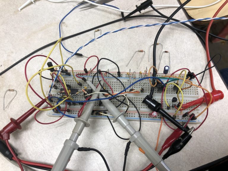
Poking at a circuit lets you see problems you didn’t know were there.
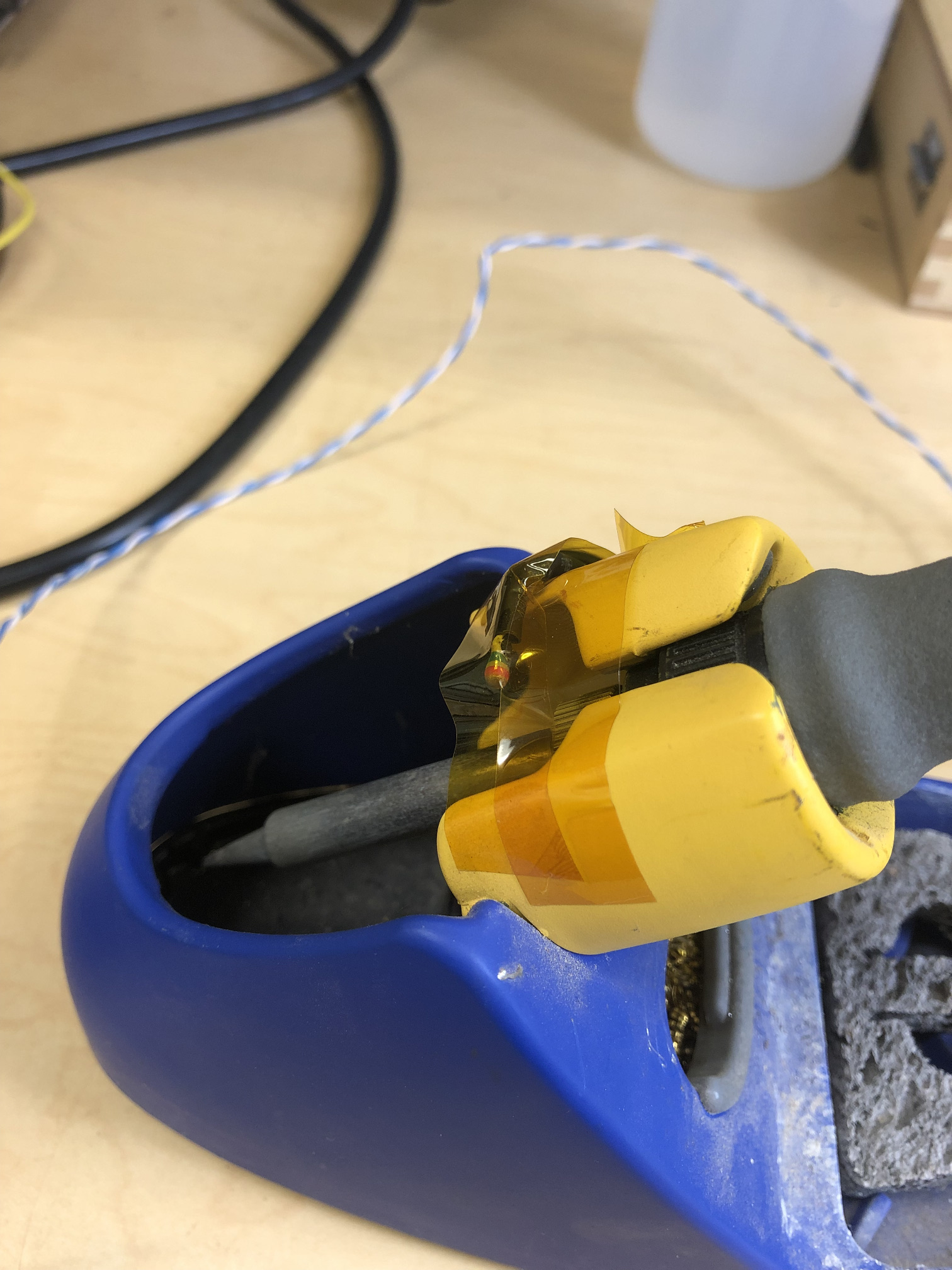
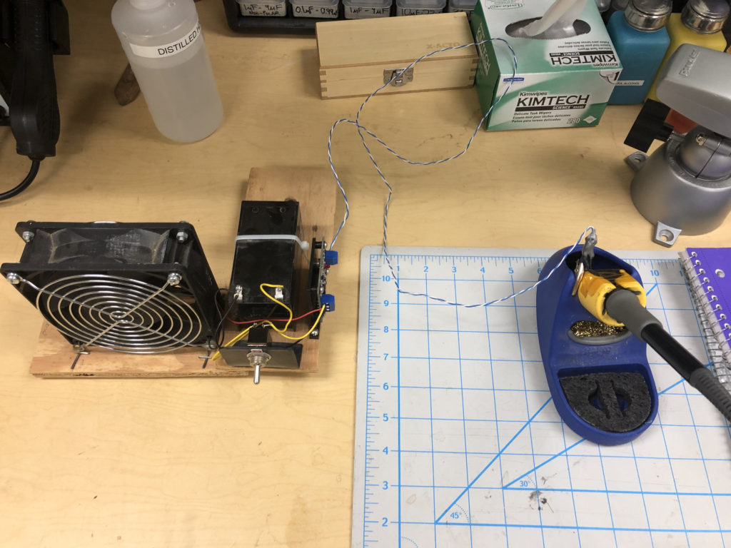
I built the circuit using one of my solderless breadboards and mounted the sensor in the location where I thought I would get a consistent signal. The mounting was done by using kapton tape. I’d come up with a removable solution later.
One of the first things I found was that the sensor circuit picked up the 60Hz soldering iron power really well. Fortunately the signal of interest is well below that frequency, so I adjusted my low-pass filters in order to squash that “noise”.
Another observation was that I had to adjust my trip points when I tested at different ambient temperatures. That led to adding a fixed resistor in parallel with the sensor to get a more linear response and adding a current source to drive the sensor.
Once I was comfortable with the design, I captured the schematic in KiCad (see Part 3) and then designed a PCB for the circuit (also in KiCad). I send the PCB for manufacture at www.oshpark.com and, since it used primarily surface mount parts, I also ordered a solder paste stencil from www.oshstencils.com (seperate businesses). I then ordered parts for the build from Digikey.
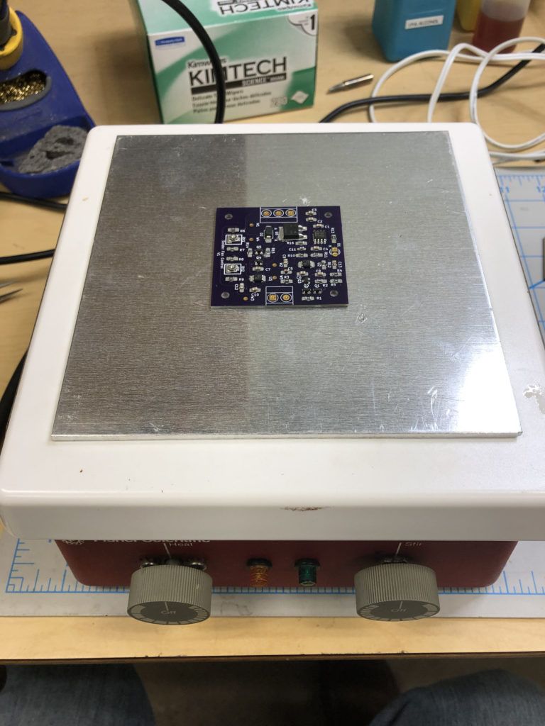
A couple weeks later everything arrived for the build. I wiped on the solder paste using the stencil, placed the components, then used a combination of a hot plate to warm the entire PCB to just under the solder melt point and then I went around the board with my hot air soldering pencil. Once the PCB cooled down I used a little bit of flux and my soldering iron to clean up a few solder bridges between the IC pins. I then soldered on the thru hole components.
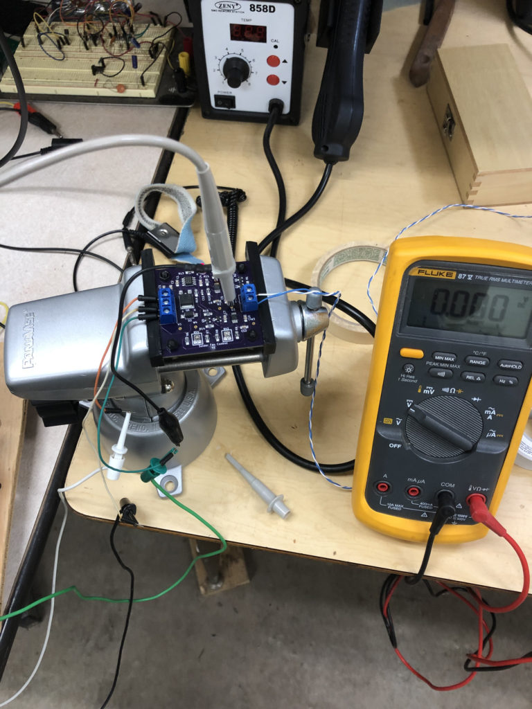
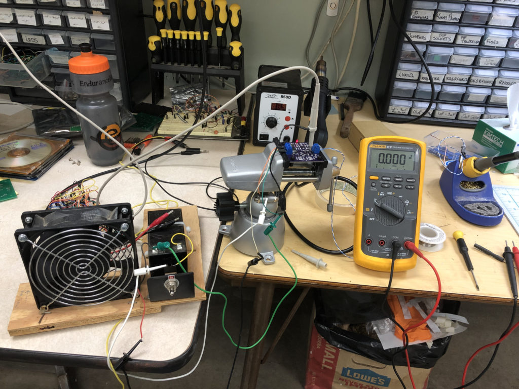
I did my initial power up tests by powering the board from a current limiting power supply instead of connecting it to the 12V battery. Then I connected the sensor and observed the conditioned temperature signal as I removed and replaced my iron.
I adjusted my on/off trip points with the trim pots and soon enough I had the LED toggling correctly every time removed and replaced the iron. I then connected the circuit to the battery and the fan, flipped the power switch, and then received that satisfying rush of success when the fan kicked on when I removed the iron!
The circuit worked pretty well, but I decided to lower the gain by reducing the value of C8 to the value shown in the schematic, since I was seeing the signal clip at both insertion and removal.
Now for some mechanical design. I needed to mount the circuit to the fan, and to do that I first designed a 3-d printable mount in Fusion360.
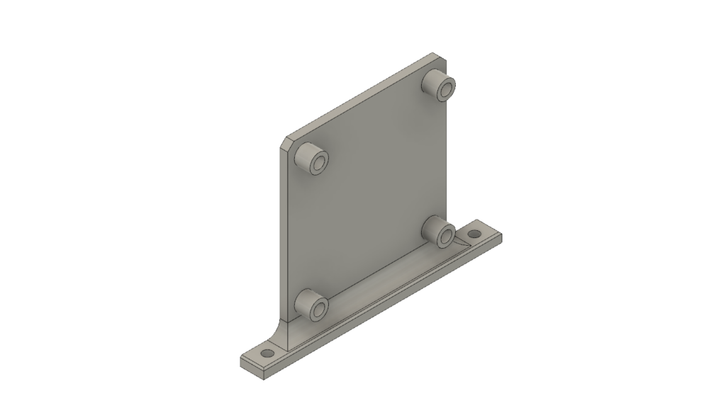
Normally I use the 3-d printers we have at my work for my personal prints (it’s allowed and encouraged), but with the office going remote-only I had to send the design out. I used the online service CraftCloud to manufacture the mount. They were fast, cheap, and the print was high quality. I hot-pressed in threaded inserts for the PCB fastener screws and mounted it by the battery.
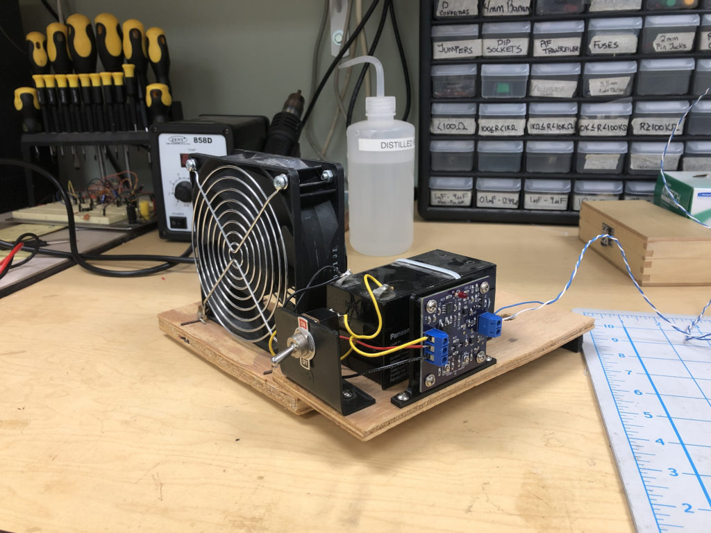
One final improvement was to epoxy the sensor to an alligator clip so I could easily remove it from the iron holder in necessary.
And there it is. I can’t say enough how much I like this tool. It really does make soldering jobs a breeze… 🙂