Circuit Design
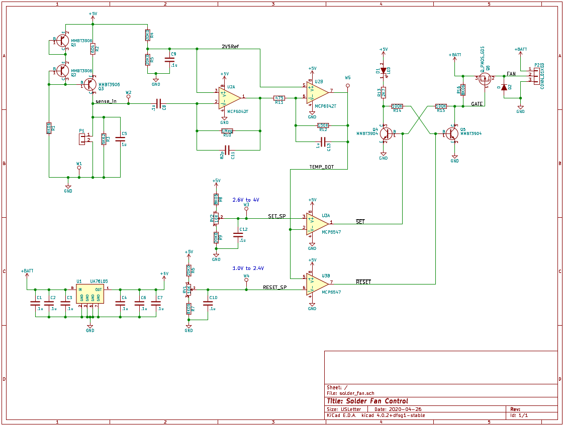
The circuit design for the controller is pretty straight forward. Q1, Q2, and Q3 form a current source which is programmed by R2. The current is fed into the thermistor sensor which connects to P1. The voltage signal from the thermistor is differentiated by C8, R10, and U2A. The output of U2A is -0.1V per V/s output of the thermistor.
The output of U2A is amplified by U2B and then is fed into two comparators. One comparator is used to detect the threshold to turn the fan on when the temperature falls. The other is used to turn the fan off when the temperature rises. Both set points are adjustable via potentiometers RV1 and RV2.
The comparators control the S-R latch circuit formed by Q4 and Q5. When Q4 is conducting, the fan is off and the indicated LED, D1 is on. When Q5 is conducting, the fan is turned on via the P-Channel MOSFET Q6 and LED is off. D2 protects Q6 from any back-EMF generated by when Q6 turns off.
The circuit is powered from a 5V linear regulator (UA78L05), which runs off the 12V fan battery.
Design Choices and Rational
The thermistor is an NTC 6.8k, part number NTCLE100E3682JB0, that I had in stock from a previous project. The 5.6k resistor in parallel with the thermistor gives the sensor an output of -60mV / Δ°C (+/-2mV) with a 1mA drive over the ambient temperature range of 15°C to 35°C.
Without the 5.6k resistor the ΔV / Δ°C output would vary from -437mV to -207mV per Δ°C in that same ambient range. The effect of this wild variability would be me constantly twiddling with the trimmers as the weather changes. No thank you!

Powering the circuit from a linear regulator instead of directly off the battery greatly simplifies the design by providing a stable power rail. If the circuit was powered directly from the battery then everything would be subjected to massive supply fluctuations when the fan turns on and off. The fan is a DC brushless motor, which means that it is not a simple load. The plot below shows the battery voltage as the fan is turned on. Note the spikes generated from the brushless fan controller.
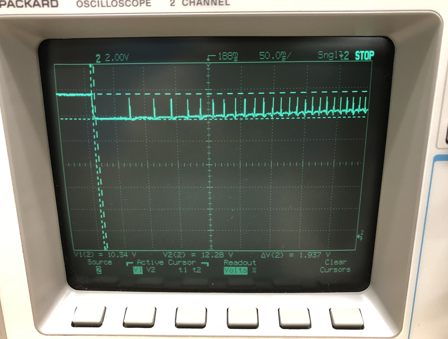
The 7805’s ripple rejection and line regulation work reduce the battery voltage spikes’ and voltage drop’s effect on the 5V rail.
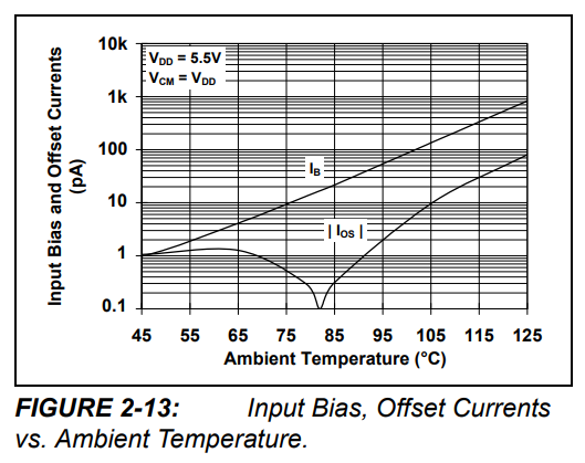
The dual op-amp is a Microchip MCP6042, which has rail-to-rail input and output range, 3mV input offset, and 1pA of input bias current (at room temperature). The input bias current is important since the first stage has a 1MegΩ impedance on the input, which could lead to large offsets if the input bias current gets out of hand. Normally I’d try to balance the impedance seen at both inputs in order to switch to battling the input offset current, but since this circuit only has to operate around room temperature and the offset current in this range is about the same as the bias, I decided it wasn’t necessary.
To be honest, the gain of the second stage combined with the offset voltage of the op-amp makes me nervous. The worst case offset leads to almost 1V offset on the output. The fact that the trip points are adjustable offers a little relief, but I may look at reducing the gain of the second stage in the future.
The dual comparator, MCP6547, has rail-to-rail input,an open drain output, and features some built in hysteresis, which isn’t critical in this application since each comparator is driving one input of an S-R latch, but does help to reduce the parts current draw around the switching threshold.
I designed in the LED to both serve as a reminder to turn off the fume fan when I’m done soldering for the day and also to indicate the state of the latch.
The P-Channel MOSFET is an IRFR9010 and is adequate for the 0.9A fan current draw. It also has a maximum Vgs(th) of -4V, so driving it when the battery voltage is drooping will not be an issue. The rated gate-source voltage is +/-20V, which means no extra components are necessary to protect the gate from over-voltage in this application.
I put in some low-pass filtering on both the sensor input and the second stage amplifier to help reduce the effect of noise pickup. I also put a small 82pF across the differentiator feedback to help ensure stability and compensate for the lag from the combination 1Meg feedback resistor and input pin capacitance.
That’s pretty much it. On to the build phase!