Detecting the presence of a hot soldering iron using a temperature sensor seems like a workable solution. The idea is to mount the sensor, a thermistor, in a place where it will be hot when the iron is in the holder and cool when the iron is removed.
A couple of points to consider are:
- Where can the probe be easily mounted?
- Can the soldering iron hit the sensor when mounted? The thermistor will be damaged if the iron contacts it too long.
- Will the sensor be in the heat path?
- What temperature set points should be used to signal the presence/absence of the iron?
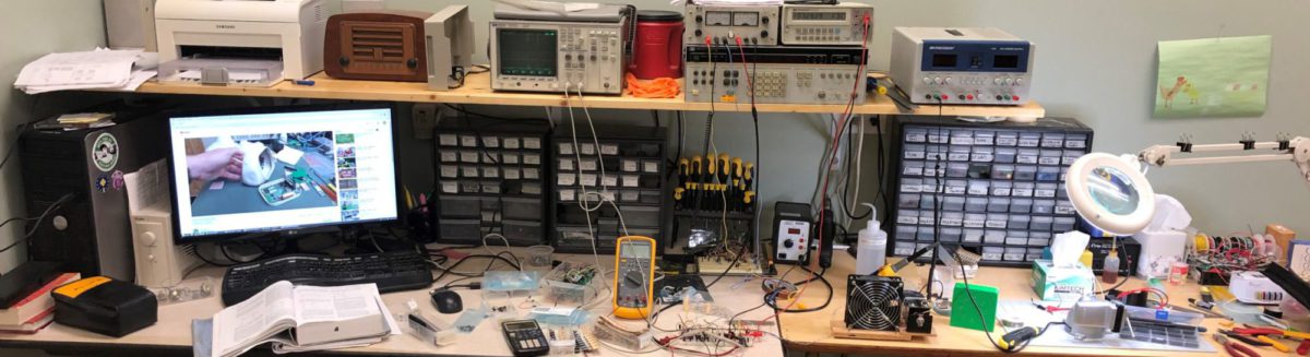
The first three points deal with where to put the sensor. The sensor needs to be placed above the iron to get the best heat signal since heat rises. The holder which came with the Hakko FX-888 has a wide open area above the iron. Mounting the sensor above the iron tip was my first idea. However, the iron tip can vary in vertical position based on whether the iron is fully seated in the holder. So to be safe the sensor would have to be mounted a fair distance, about an inch, above the iron tip in order to ensure the iron tip doesn’t directly contact the sensor.
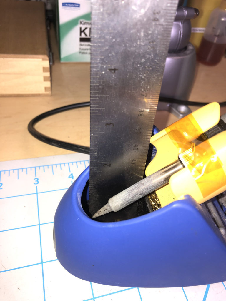
That causes two problems. The first is that you don’t get as large of a temperature difference when the sensor is that far away from the sensor. The second is that it would require a fair amount of shielding (wind blocking) in order to keep the sensor in the heat path. After all, there will be a powerful fan running nearby. I landed on mounting the sensor near the base of the iron on the stand. In this location the sensor can be mounted close to the base of the iron without risking it being contacted during iron removal/replacement.
The last bullet point really sets the detection strategy. What temperature should the fan turn on, and what temperature should it turn off? Using absolute temperature set points seemed destined for failure. My lab is in an environment that gets hot during the summer and cold in the winter. Its true that it doesn’t get as hot as a soldering iron tip, but the sensor can’t directly contact the tip and there will be a fairly steep temperature gradient in free air.
Using a relative temperature measurement seems like it could work. The problem is that it would either require two temperature sensors or a thermocouple (which is a relative temperature sensor). Another problem in using absolute temperature or relative temperature is the response rate of the sensor itself. I want the fan to turn on as soon as the iron is removed and turn off when it is put back. Even a small gauge thermocouple will have some lag due to the still air surrounding it.
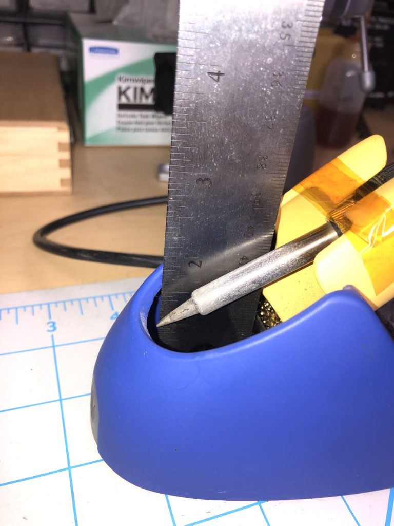
To illustrate this, I fired up my HP3497A DAU and fixed a thermocouple above the tip of my soldering iron and measured the temperature as I removed and replaced the iron from the holder.
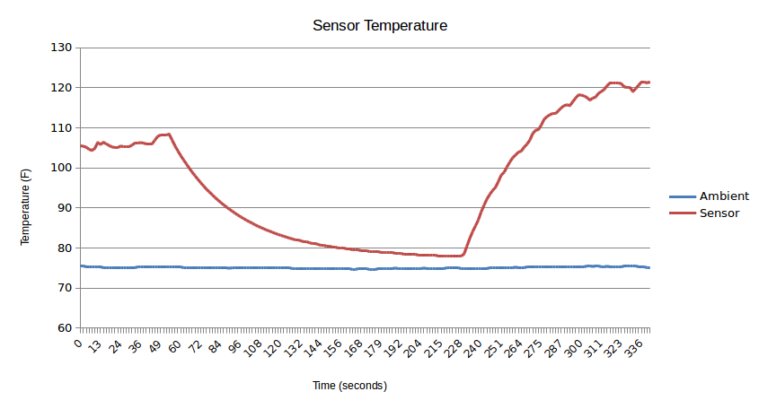
You can see that it takes a few seconds for the sensor to reach steady state. The time constant in these measurements (time it takes to reach 63% of final value) is 40 seconds! Also, I believe that the either the sensor moved a bit when I replaced the iron or the iron wasn’t in fully and ended up closer to the sensor; note the increase in steady state temperature.
Picking static trip points for all lab conditions (summer and winter) would not be easy. Even though the sensor is pretty close to the iron tip, the temperature rise is only about 30 degrees.
However, looking at the graph, it is clear when the iron is removed and when it is replaced by using the direction/magnitude of the temperature change. Therefore I decided to use the rate of change (derivative) of the temperate signal in order to detect the iron removal/replacement.
Now, time to design the circuit 🙂